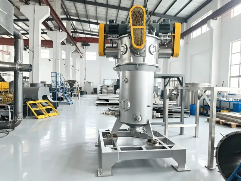
 Fluid energy
Particles grind each other
Nozzles fire compressed air into a flat spiral chamber. Particles accelerate into each other and shatter on collision — the machine has no moving parts and nothing but air touches the product at grinding speed.
- Mechanism
- Fluid energy
- Fineness
- D50 1 – 10 µm
- Capacity
- 20 – 800 kg/h
Working principle
Built-in centrifugal classification lets only finished fines escape the centre outlet; oversize keeps circulating. That is how it holds a D50 of 1–10 µm for APIs, pigments and ceramics.
What the material passes through
- 1Venturi feed injectorCompressed air pulls the feed into the chamber
- 2Grinding nozzlesAngled jets set up the high-speed spiral
- 3Spiral grinding chamberCeramic or PU lined — particle-on-particle impact zone
- 4Classification zoneCentrifugal force returns oversize to the jets
- 5Cyclone + bag filterRecovers the micronised product from the air
What is a Jet Mill?
A fluidized bed jet mill is an advanced, fluid-energy grinding machine designed for the ultra-fine micronization of powders down to the sub-micron and single-digit-micron range (D50 from 1–10 µm). THOR by CI engineers the series to operate without any mechanical grinding media or physical screens.
This technology is the benchmark for high-purity grinding — producing sub-micron powders with no grinding media and no metallic wear, the preferred ultra-fine pulverizer for battery materials, specialty chemicals and advanced active pharmaceuticals.
Where Jet Mill sits on the particle-size scale
Advantages & limitations
Where fluid energy is unmatched — and the auxiliaries it demands.
Advantages
Zero metallic contamination
Autogenous grinding and ceramic linings prevent metallic pickup — ideal for EV battery graphite and silicon anode materials.
Isothermal grinding (self-cooling)
Compressed-air expansion absorbs heat (Joule-Thomson), keeping the chamber cool and protecting heat-sensitive APIs.
Precise sub-micron separation
The integrated classifier wheel produces clean, narrow PSD curves with no coarse oversize fraction.
No mechanical wear components
No gears, pins or screens — virtually no mechanical maintenance and immunity to hard-material damage.
Limitations to plan for
Substantial auxiliary equipment
Needs a steady supply of oil-free compressed air — rotary-screw compressors, air receivers and refrigeration dryers.
High specific energy consumption
Compressing air for fluid-energy milling costs significantly more energy per ton than mechanical impact mills.
Strict feed-sizing limits
The fluidized bed can't take coarse feed — material must be pre-milled below 1.5 mm for efficient fluidization.
Milling, mixing & bulk handling
The THOR-JM Series runs under continuous negative pressure — no dust escapes into the factory atmosphere.
Hygienic feeder integration
Double-flapped sanitary rotary valves or loss-in-weight twin-screw feeders introduce powder without losing pressure.
Sub-micron cyclone receivers
Output is conveyed to multi-stage cyclones and pulse-jet baghouses with PTFE membrane filters that capture sub-micron particles.
Closed-loop gas circuits
For explosive or toxic materials, run nitrogen or argon in a closed recycling loop with continuous O₂ monitoring and makeup.
How it sits against the other four
| Spec | Pin Mill | Hammer Mill | Jet Mill | Ball Mill | Air Classifier |
|---|---|---|---|---|---|
| Mechanism | Impact · screenless | Impact + screen | Fluid energy | Attrition + impact | Centrifugal cut |
| Fineness | 20 – 200 µm | 200 µm – 5 mm | D50 1 – 10 µm | 20 – 200 µm | D97 3 – 200 µm |
| Capacity | 10 kg/h – 10 t/h | 2 – 25 t/h | 20 – 800 kg/h | 0.65 – 80 TPH | 0.5 – 20 t/h |
| Strength | Narrow size spread | Rugged throughput | Finest, contamination-free | Wet or dry, hard feeds | Sharp cut point |
| Best for | Food, pharma, soft chemicals | Grain, biomass, ore | API, pigment, ceramic | Clinker, minerals, refractory | Downstream of any mill |
Technical specifications & model range
Six frame sizes. Final sizing is confirmed after pilot trials with your actual feed material.
| Model | Chamber diameter | Compressed air flow | Rotor speed | Avg capacity |
|---|---|---|---|---|
| TH-JM-150 | Ø160 mm | 3.7 – 7.5 m³/h | 6000 – 18000 rpm | 10 – 50 kg/h |
| TH-JM-300 | Ø250 mm | 11 – 18.5 m³/h | 4000 – 12000 rpm | 100 – 800 kg/h |
| TH-JM-500 | Ø400 mm | 30 – 45 m³/h | 2500 – 7500 rpm | 800 – 1800 kg/h |
| TH-JM-800 | Ø630 mm | 55 – 90 m³/h | 1600 – 4800 rpm | 2000 – 4000 kg/h |
| TH-JM-1000 | Ø800 mm | 100 – 160 m³/h | 1200 – 3600 rpm | 4000 – 7000 kg/h |
| TH-JM-1200 | Ø1000 mm | 160 – 250 m³/h | 1000 – 2800 rpm | 7000 – 10000 kg/h |
Specifications are typical and subject to change. Final sizing confirmed after pilot trials with your feed material.
Turn it around yourself
The production machine, modelled from the SolidWorks assembly — drag, orbit and zoom into it right on this page.
What we keep on the shelf for you
Every wear part is made in Nonthaburi and ships immediately, backed by our own service crew.
- Nozzle setsTungsten carbide inserts
- Chamber linersAlumina ceramic or PU
- Filter bagsAntistatic and food-grade media
- Gasket kitsFull sealing set per size